Search
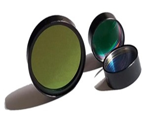
optical filter for PCR Fluorescence Detection
Products
- Principle of PCR Fluorescence Detection
- PCR (quantitative polymerase chain reaction) is based on the principle of adding fluorescent probes or dyes during the PCR reaction to dynamically monitor changes in fluorescence signals during the nucleic acid amplification process, thereby enabling quantitative analysis of the initial template. This process requires the use of optical filter to aid in the collection of fluorescence signals. Ordinary PCR only performs amplification without real-time detection and does not require the use of optical filter.
- PCR optical path design
- Typical optical path configuration: light source (laser/LED/halogen lamp) → excitation filter → sample → dichroic mirror → emission filter → detector (PMT/PD).
- 1. Side-illumination optical path (lateral excitation / lateral detection).
- 2. Confocal Optical Path (Confocal).
- 3. Filter Wheel Optical Path.
- 4. Multi-channel parallel optical paths (multiple sets of filters, multiple detectors).
- 5. Fiber-coupled optical path.
-

- The Core Role and Types of optical filter in the PCR Optical Path
- Because the fluorescence signal is very weak, stray light from the sample cell, tube wall fluorescence, reagent autofluorescence, and ambient light interference can seriously interfere with the collection of fluorescence signals. Therefore, it is necessary to use optical filter for filtration. Filters are key components that determine the sensitivity of PCR instruments; they can greatly improve the signal-to-noise ratio (SNR), allowing the instrument to detect weak fluorescence signals, thereby significantly enhancing detection sensitivity.
- 1. Excitation filter: Only allows light signals of specific excitation wavelengths to pass through.
- 2. Dichroic mirror: reflects excitation light, transmits fluorescence, usually used at a 45° angle.
- 3. Emission filter: only transmits the target fluorescence signal, blocking the excitation light and stray light in the optical path.
- 4. Multi-channel filters (MBP): A multi-channel parallel optical path design can use multiple sets of single-channel filter groups arranged in parallel, or directly select multi-channel filters, making the instrument structure more compact.
- Key Parameters of Common Fluorescence Channels and Optical filter in PCR
- The excitation filter spectrum type is usually a band-pass filter, and the emission filter spectrum type can be a band-pass filter or a high-steepness long-pass cutoff filter. The dichroic mirror is an interference cutoff filter designed for 45°, and the spectrum types include long-pass filter and short-pass filter.
-
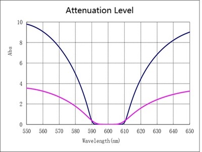
- Attenuation Level (OD): Thin-film interference filters mainly block light through reflection. The term 'optical density (OD)' describes the attenuation level of background stray light more accurately. Absorbance (Abs): Calculated the same way as optical density, it indicates the efficiency of light absorption.
-
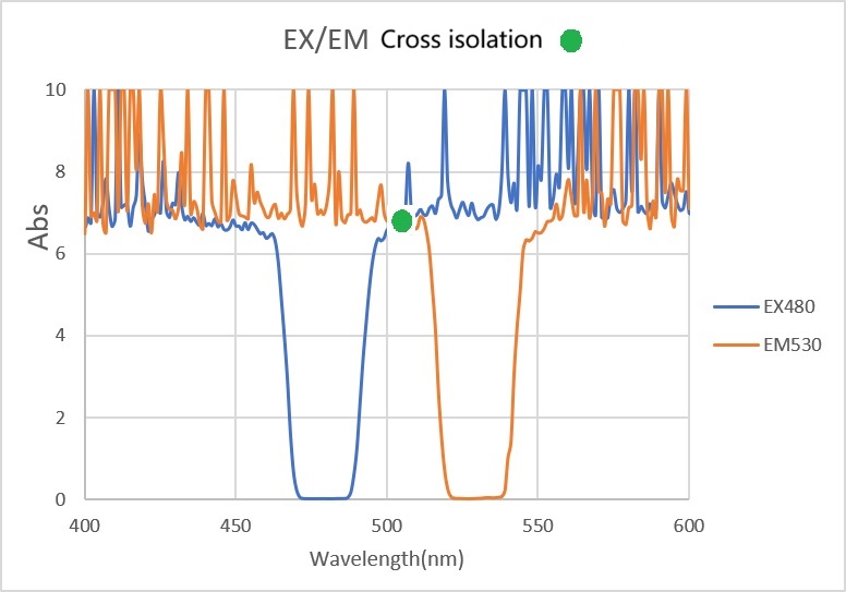
- Cross isolation: It describes the minimum attenuation level at the intersection of the excitation and emission filters (within a specific range). This value is important when matching excitation and emission filters in a combination of fluorescence filters, as it shows how well the two are isolated from each other without interference.
-
- Slope: Describes how sharp the transition is from pass-through to cutoff in a bandpass or cutoff filter. The slope can be specified by stating that the filter must have a certain blocking level at a specific wavelength.
- Angle of Incidence (AOI): Most types of filters, like thin-film interference coatings, are 'angle-sensitive,' which means their spectral characteristics change with the angle. If you’re going to use a filter in a converging or diverging beam, you might need to specify the half-angle of the incoming light. For dichroic mirrors with non-perpendicular incidence, you need to consider polarization separation, and how it works depends on the design and the wavelength of the incoming light.
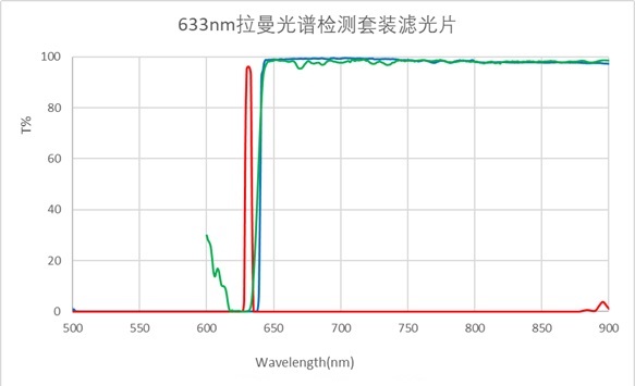
- Steepness and verticality: The 'verticality' of a spectral signal is also important because it allows for a sharper transition from high transmittance in the passband to high OD attenuation. The squarer the shape of the filter, the steeper the edge of the bandpass (or cutoff) filter. This is especially important in Raman spectroscopy. Designing bandpass filters with steeper slopes or higher verticality can be achieved simply by adding more cavity layers to the filter.
-
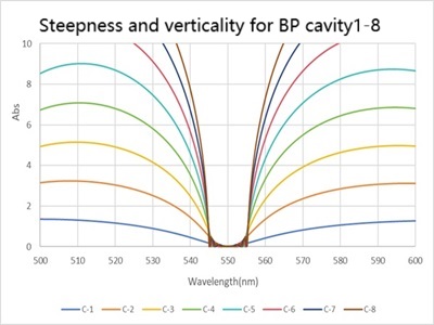
- Passband ripples and insertion loss: Adding more cavity layers might cause unwanted ripples and loss in the passband, which can lower the contrast of the final image. This issue can be addressed by optimizing the layer thickness and improving monitoring accuracy.
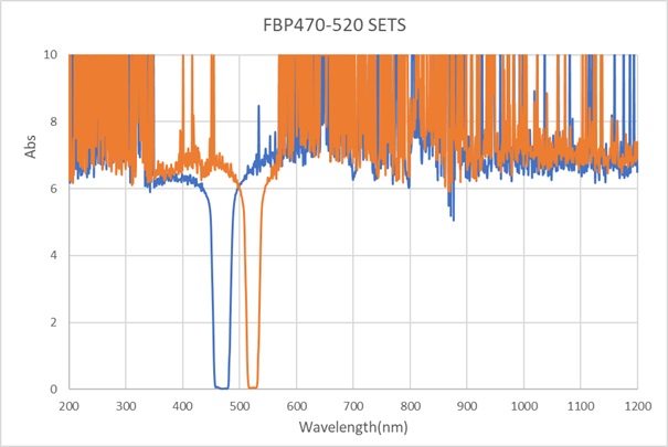
- Different fluorescence detection channels correspond to different fluorescent dyes or fluorescent probes, with each channel corresponding to a set of excitation and emission filters. For example, FAM / SYBR Green excitation: 470 nm, emission: 520 nm; VIC / HEX / JOE excitation: 530 nm, emission: 570 nm; ROX excitation: 580 nm, emission: 610 nm; Cy5 / Texas Red excitation: 620 nm, emission: 680 nm.
- Key indicators of fluorescent detection bandpass filters: center wavelength (CWL), full width at half maximum (FWHM), blocking depth, blocking range, steepness, etc. These spectral indicators directly affect the sensitivity of fluorescent signal detection. Maxoptics.cn can customize various types of spectral fluorescent detection filters according to customer requirements.
-